

TerraDat is a specialist Seismic refraction survey company with many years of experience applying and researching its use in shallow engineering and geotechnical work.
Seismic survey methods provide a useful tool for investigating geological structure and rock properties. The technique involves the observation of a seismic signal that has been refracted between layers of contrasting seismic velocity, i.e., at a geological boundary between a high-velocity layer and an overlying lower-velocity layer.
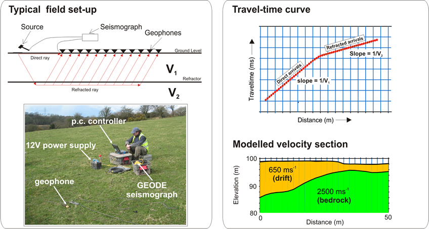
A TerraDat seismic survey involves deploying shots at the surface and recordings made via a linear array of sensors (geophones or hydrophones). The shots may be a shotgun, accelerated weight drop or explosive.
Refracted seismic signals travel laterally through the higher velocity layer (refractor), generating a ‘head-wave’ that returns to the surface. Beyond a certain distance away from the shot, the signal that has been refracted at depth is observed as the first-arrival signal at the geophones. Observation of the travel times of refracted signals from selectively deployed shots enables the derivation of the depth profile of the refractor layer. Shots are typically fired at locations at and beyond both ends of the geophone spread and at regular intervals along its length.
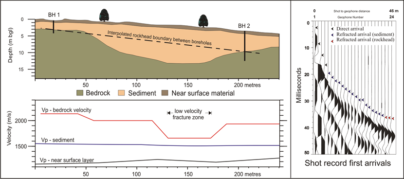
The results of the seismic refraction survey are usually presented in the form of seismic velocity boundaries on interpreted cross-sections. Seismic sections represent the measured bulk properties of the subsurface and enable correlation between point source datasets (boreholes/trial pits) where underlying material is variable. Reference to the published seismic velocity tables enables derivation of rippability values.
The data processing is carried out using specialist seismic software. The first stage involves the accurate determination of the first-arrival times of the seismic signal (time from the hammer blow to each recording hydrophone) for every shot record, using PICKWIN. Time-distance graphs showing the first-arrival times were then generated for each seismic shot record and analysed using PLOTREFA software to determine the number of seismic velocity layers. Modelled depth profiles for the observed seismic velocity layers are produced by a tomographic inversion procedure that is revised iteratively to develop a best-fit model. The final output of a seismic refraction survey is a velocity model section of the subsurface based on an observed layer sequence with measured velocities that correspond to physical properties such as levels of compaction/ saturation in the case of sediments and strength/rippability in the case of bedrock.
Constraints
Layer velocity (density) must increase with depth; true in most instances. Layers must be of sufficient thickness to be detectable. Data collected directly over loose fill (landfills) or in the presence of excessive cultural noise may result in sub-standard results. In places where compact clay-rich tills and/or shallow water have overly weak bedrock, an S-wave survey may be used to profile rockheads where insufficient velocity contrast may prevent the use of a P-wave survey.