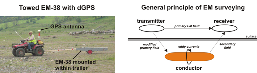
A ground conductivity or electromagnetic (EM) survey involves the generation of an EM field at the surface and subsequent measuring of the response as it propagates through the subsurface. The main components of the instrument are a transmitter coil (to generate the primary EM field) and a receiver coil (to measure the induced secondary EM field). The secondary field’s amplitude and phase shift are recorded and then converted into values for ground conductivity and in-phase component (metal indicator).
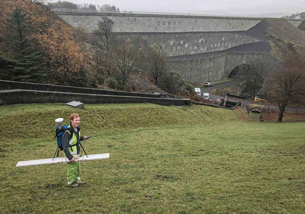
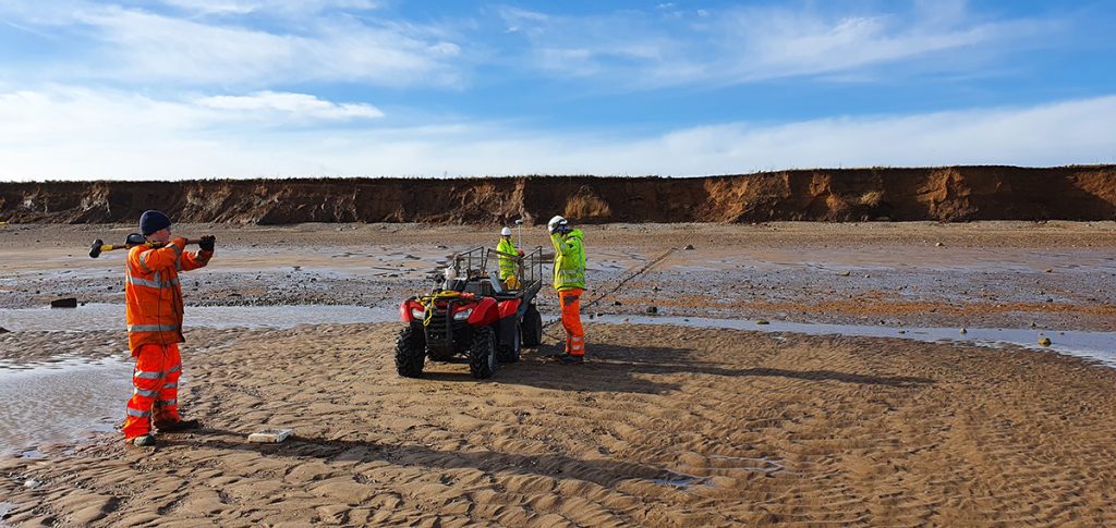
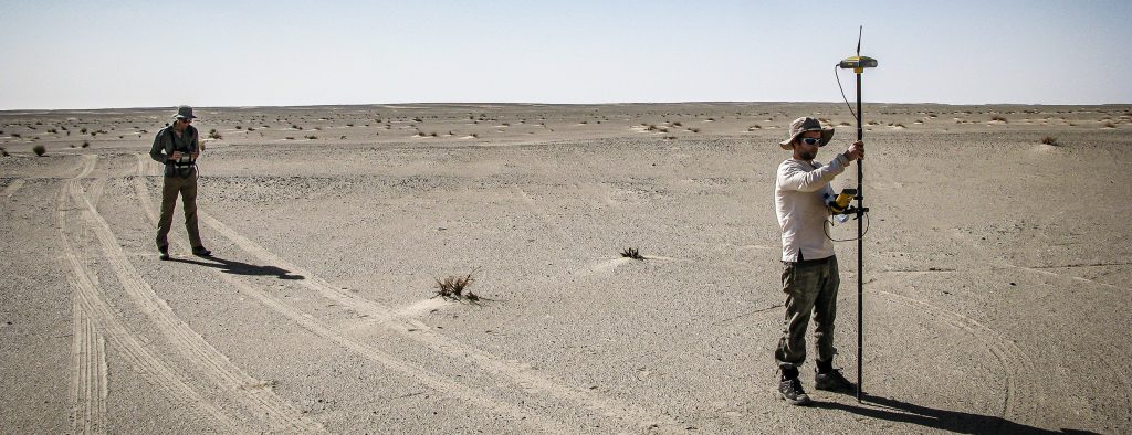
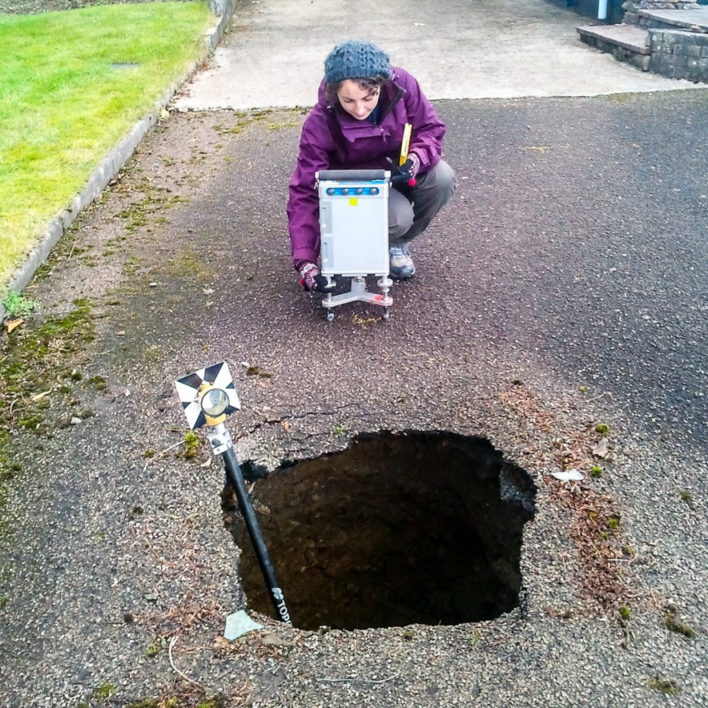
The ground conductivity (EM) instruments are either hand-carried or mounted/towed behind a quad bike. Readings are usually taken on a regular grid or along selected traverse lines, and positional control can be provided by dGPS if there is sufficient satellite coverage.
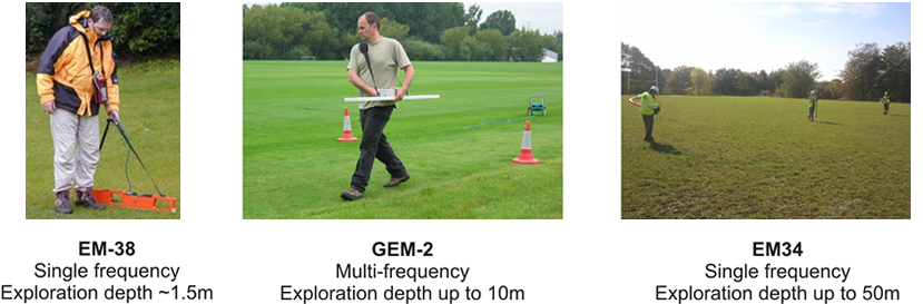
The selection of the particular EM instrument (EM-38/EM-31/GEM-2) is primarily based on the required penetration depth of the survey. However, for most conductivity surveys, the GEM-2 has replaced the more conventional EM-31 instrument due to its ability to simultaneously acquire data at different frequencies (i.e. different depth levels) and a greater depth of penetration. At each survey’s end, the data is downloaded to a field computer and corrected for instrument, diurnal and positional shifts. Additional editing may be carried out to remove any ‘noisy’ data values/positions.
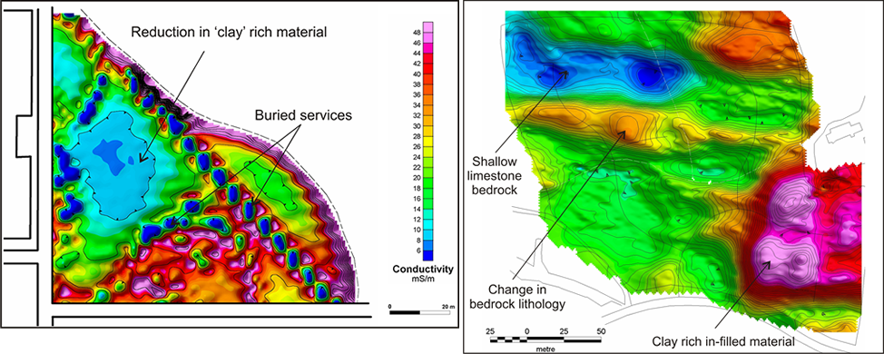
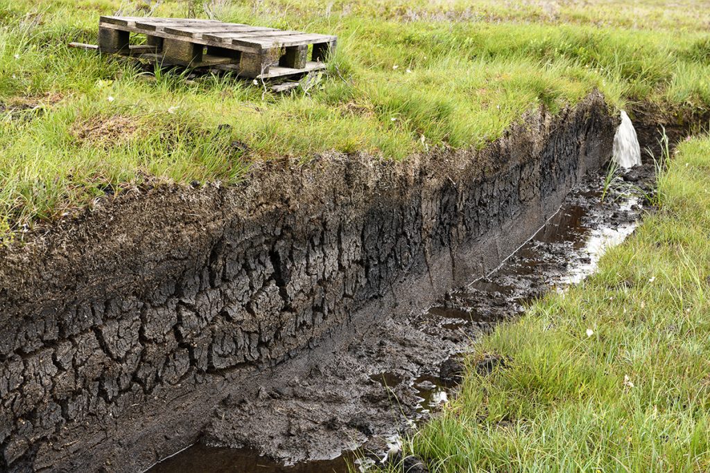
The results from the EM survey can be presented as colour-contoured plots of conductivity and in phase (metal response) data. In general terms, a relative increase in conductivity values usually indicates a local increase in clay content or water saturation. However, if there is a corresponding increase in the inphase response, the influence of some artificial source (i.e. metal) is likely.